I'm going to start with a bit of back story to explain why I went this direction instead of a more traditional approach of buying a whole house fan or even the similar commercial product like
the Aircycle, so if you would rather skip to the how to it starts in paragraph 6 with the shopping list. I also provided some rough schematics for the cabinet here.
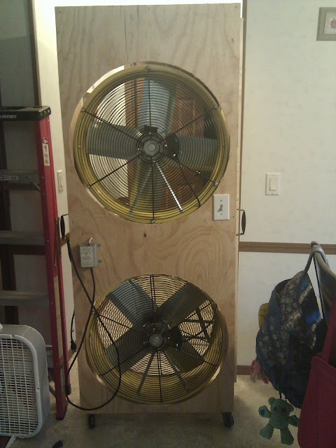 |
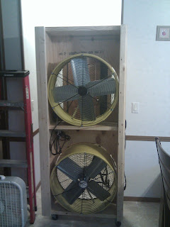
| Here is a picture of the mostly finished product. I plan on staining and sealing it, but I wanted to put it into use. |
|
My Wife and I bought a house when we were 18 and 19, if we had it to do over again we would do it differently, but we don't so for now we are living in the double wide trailer that we purchased and put on a new foundation on a half an acre we bought from my uncle. There isn't anything really wrong with the house and it has served us well as a dwelling, that said I would like to have a basement, and a handful of other little things I would do differently if I had the option to go back and build a house instead. Financing for a trailer is highway robbery over financing an identical built home as well, higher interest rates and mandatory PMI for the life of the loan for example.
The trailer is about 1450 sq ft has vaulted ceilings and is really, really well insulated, my only complaint with that is my attempts to use window fans and box fans to pull in night air to keep the house under 80 during the day without kicking on the air conditioner have failed. Even when it gets down to 50 degrees at night I am only able to vent enough hot air to get down to about 70 if the house is starting at 80. The ultimate solution to this problem is a large whole house fan mounted in the ceiling that blows massive amounts of air into the attic and out the roof or side vents in the attic drawing cool air in through the windows or doors that are open in the house. However with a vaulted ceiling there isn't much open attic space out on the outside edges of the house. With the lay out of the house the fan would have to go in the living room or the kitchen in the middle of the house to get enough space between the ceiling and roof to get good ventilation to the attic vents already in the roof, logistically and cosmetically this isn't a very viable option.
I climbed up on the roof to see if I could maybe boost the bathroom exhaust fans with some larger in line duct fans to do the job, no luck, they were vented using small 3" pipe and I don't think I could get a high enough velocity fan in that would fit in the small pipe to do the job for a reasonable price.
I then decided that something like my "suction tower", as I'm calling it, was pretty much the only option. First I searched for a commercial option, because I don't have enough time in my schedule to do the projects I want to do as it is. The only thing I could find was the "Aircycle" that I linked to earlier, and for $400 I would want it to move much more air than it does. The suction tower cost me around $300 out of pocket because I had most of the small ticket items like screws, switches, wire, and electrical boxes just laying around from other projects. Someone should be able to reproduce this for under $400 from scratch and get a fan that can move up to 8000 CFM instead of 1700. That is over 4.5 times the volume of air moved with only a little over 2 times the energy usage, plus if you only use one fan on low you get around 2 times the air moved with the roughly same electric used as the Aircycle on high. After doing more research for this post I realize I should have purchased
This fan as it moves almost twice the CFM for roughly the same price as
the ones I bought at my local Orschlens after shipping. If you use the ones from northern tool you may have to modify the width of the cabinet to get them to fit right, I don't know the exact dimensions of that fan drum, but I would suggest using the Flow Pro fans as you get more bang for you buck with some minor modifications to my plans.
Shopping list for this project. Admittedly I would use different fans as I explained in the previous paragraph.
- 2 12 foot 2x10s
- 1 12 foot 2x4
- A 4x8 foot sheet of 3/8" plywood
- A couple standard electrical boxes
- A standard 110v house electrical outlet
- A light switch
- Wall plates for the outlet and switch
- A 10 foot 3 prong extension cord at least 14 gauge wire
- Possibly some wire nuts
- Some Romex connectors
- 2 of These fans.
- 4 casters, the ones I used are 3" tall (if you use any other size you will need to keep that in mind when you cut the 2x4s and the 2x10s for the sides.
- *Optional: a Thermostat from an attic fan* (Make sure it can handle the load of 2 of these fans.)
1. Start out by measuring your door opening write down your measurement from the floor to the bottom of the door frame. Subtract the height of the casters from this number, in my case I started with 74 inches minus my 3 inch casters leaves me with 71. Measure the width with the door all the way open as well, if it is less than 32 inches you will have to use 1 by lumber and be much more careful with it when assembling as it is easier to splinter and crack, and less sturdy than 2 by lumber. If it is less than 30 inches this will not work for you at all.
2. Cut 2 2x10s and 2 2x4s to the calculated number from step 1, once again 71 inches for me. Use a table saw and cut an inch off the long edge of the 2x4s leaving you with 2 boards that should measure 1-1/2 inches x 2-1/2 inches.
3. Measure the depth and width of the groove that your door slides into on the door frame when shut, mine was 1 inch wide and 1/2 an inch deep, I cut a 1/2 by 1/2 inch corner out of one of the trimmed down 2x4s to leave a 1 inch by 1/2 inch tab that will slide into the groove the door does when it is shut. Here is a picture to kinda show you what I am talking about.
 |
| The 2x4 that is nearest the camera has a corner trimmed out so it will fit in the door frame where the door would when closed. |
4. You need to cut 3 2x10s to the length of your fan's Diameter, mine were 26 inches.
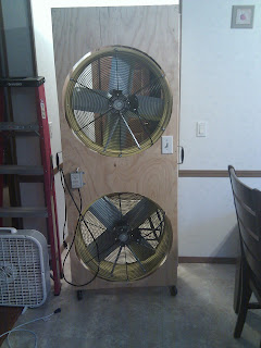
5. Now you need to assemble them into the cabinet pictured below, I used 3 inch screws here, and the middle shelf is just that, right in the middle of the cabinet centered 35-1/2 inches from either end.
6. Now would be a good time to put the casters on as well, you want them as close to the corners as you can get, I used 1 inch long screws here as anything longer would have went through the 2x10.
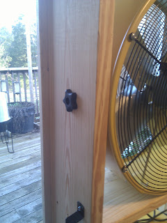
7. Attach the 2x4's to the face of the tower you want facing out the door, be sure the grooved out side is on the side that will be against the door frame. Line them up so they hang out on either side to allow you to slide them in the groove in the frame and close the door on the other side to provide support so the tower doesn't blow itself over in the middle of the night and scare you to death.
8. You should probably install the electrical next as getting around the fans to mount the outlet box is a pain, I didn't do it that way as evidenced in the pictures, but it was 10 at night after a full day of work and my brain wasn't firing on all cylinders, that is also why the pictures aren't the best for explaining the step I'm trying to.
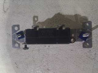
8.1 Anyways, you will take and cut the part of the cord you plug into off strip the insulation back about a 1/4 to 1/2 inch and wire it to the outlet in the box, most outlets have a guide telling you which side is supposed to be black wire and which is supposed to be white printed right on them, and green is always ground.
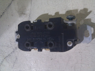 |
| Here is the back side of a standard outlet, you will want to attach the black to one side the white to the other and the green to the green screw terminal. |
8.2 The switch is not 100% necessary as these fans have their switches right on the back of the fan so they are easy to get to even after the cabinet is closed up, but I put it in anyway. You will strip off the outer insulation of the cord for about 2 inches and cut the black wire in the middle of the exposed section but not the white or green. Push the stripped off part of the cord into the switch box and pull it out the front far enough to wire it to the switch, strip the black wires back 1/4 to 1/2 an inch and wire them to one post on the side of the switch each. Strip a section of the green insulation off and loop the wire around the ground terminal then tighten the screw.
 |
| Here is the back side of a standard switch you will want to hook one black to the top terminal the other to the bottom and loop the green around the green screw terminal. |
8.3 This step is also optional, but I wanted a thermostat on it so it wouldn't get too cold in the house at night, so I wired in an old attic fan thermostat I happened to have laying around. Wiring on the thermostat is the same as the switch, cut the black and hook them to both connections on the thermostat leave the white in tact and strip a bit of insulation off the green and loop it around the ground terminal and tighten it down.
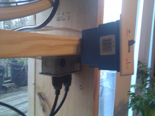 |
| This one was taken the following morning after I realized I hadn't gotten a picture of the outlet placement, I mounted it close to the inside of the cabinet and underneath so if it rained it wasn't getting directly wet. |
9. Take your fans out of the little cart they are mounted in, keep the bolts and knobs as you will use them to mount them in your cabinet.
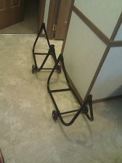 |
| Here is a shot of the empty carts |
10. Take the guard off the front of the fans, and remove the carrying handles from the outside as they will be in the way when you go to mount them in the cabinet. NOTE: Unplug them first, the blades are semi-sharp and I'm not responsible if you lose some fingers because you bumped the switch while messing around in the fan.
11. Place the fans in the cabinet where you want them, line the back of the fan up to the inside edge of the cabinet. Make sure you have them facing so they will be blowing out of the house when the cabinet is lined up in the door. Spin them so that the hole that the bolts where in for mounting them to the carts are up against the sides of the cabinets, take a pencil from the inside and mark where they are.
 |
| You can see the bolt coming out of the fan here and into the cabinet frame. |
12. Remove the fans.
13. From the inside drilling out put 3/8 or 1/2 inch holes in the center of the marks. (3/8 will work but you will need to be more precise on placement and if the hole is level or not as that is the exact diameter of the bolts)
14. You will need to go to the outside now and counter sink the holes so you can use the knobs that were threaded on the mounting bolts as the bolts aren't quite long enough to reach all the way out to the outside of the cabinet. the round part of the knob is 1 inch in diameter so take a 1 inch bit and drill about half way through the board from the outside in the holes you made from the inside out.
15. Set the fans back in, line up the holes and push the bolts through their mounting holes and the cabinet, thread the knobs on from the outside until they are nice and tight. Once done mount the guards back on the fans.
 |
| Should look something like this when you're finished. |
16. Now measure the outside dimensions of the inside face of your cabinet, mine was 71x28-3/4 inches.
17. Cut a piece of plywood to the dimensions in step 16
18. Measure from the top of the cabinet to the middle of the top fan, mine was 21-5/8 inches, write it down.
19. Measure from the top of the cabinet to the middle of the bottom fan, mine was 56-5/8 inches, write it down.
20. Measure from the side of the cabinet to the middle of both fans they should be the same number, mine was 14-1/2 inches, write it down.
21. Go to your plywood and make a mark at the measurement from step 18 down from the top and the measurement from 20 in from the side, do the same with the measurement from steps 19 and 20.
22. Now mark a circle using the radius, or half the diameter of your fan and the center points you just marked on the plywood. I used a bit of string tied to my pencil at 13 inches out and anchored at the middle point with a push pin and drew my circles for the top and bottom fans. This step takes a bit of practice and a string that doesn't stretch is a must.
23. Cut out the circles carefully, I used my router as I don't have a jigsaw, but ideally you would be using a jigsaw for this.
24. Mount your plywood to the inside side of the cabinet, make sure your holes for the fans line up with the fans. It doesn't have to be perfect, but the closer to perfect you get it the better results you will get from your fans.
25. Cut a hole for your switch box and mount it in the hole, I had to un-wire and re-wire it but I got it working at 11 the night before without adding the plywood and called it a night, I added the plywood like I originally planned the next day, and I will talk about the benefits of adding the ply in the conclusion.
26. Mount your thermostat somewhere where it will get the air from inside the house pulled across it constantly so that it is getting a sample of what temperature your house actually is. I put mine on the inside between the two fans and it seems to be working ok there.
27. I took a zip tie and tied all the cords together and tucked them up under the middle shelf and it doesn't look too bad that way, I would recommend doing something to tidy up the cords cause having them loose could cause some problems.
28. Plug it in, put it in the door, slide the door shut around it, and test it out.
Here are some more shots of the mostly finished product
 |
| Inside view |
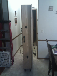 |
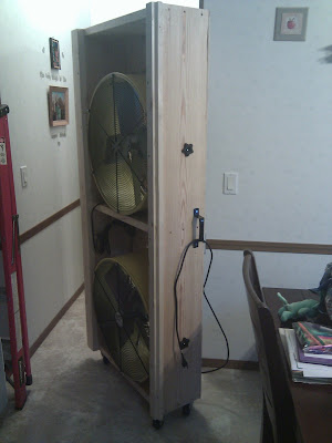
| Door side view |
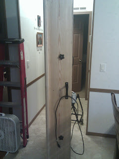 |
| Frame side view |
 |
| Outside view |
I added the handles from the fans to either side of the tower in the middle to give you a good place to grab it and move it around from. It is a bit top heavy but if you are careful it is pretty stable while it is rolling around, once it is in the door however it is solid, and you can cut and place a block behind the back side of your inside sliding door to essentially lock the fan in place giving you security if you need it. When it isn't in use I can just roll it to the side since it is on casters and close the door.
As mentioned in step 25, I ran it the first night without the plywood because I was beat after a full day of work and running some personal errands, I got it operational and went to bed. I noticed significant blow back from the fans as it wasn't sealed into the door so a lot of air was essentially looping around right at the door, adding the plywood stopped most of this, and the closer you can get your ply cut to the right spot and size the better your results with this will be. I am planning on adding a bit of weather stripping to seal the gap between the fan and plywood so that it is even tighter. There was also a significant noise reduction by adding the plywood as much of the fan noise from the outside of the fan is blocked by it. I measured the decibels from 2 feet after adding the ply and with both fans on low it runs about 85db, or about the same as a busy street, and both on high is a bit too loud at 105db, or similar to a lawnmower. I didn't measure without the ply but I can tell you that before on low was close to the same noise level as after on high so adding the ply essentially dropped the noise level 20db. Once you get about 8 feet away from this you can carry on a normal conversation without needing to raise your voice when it is on low, which is plenty of air movement for normal situations. I feel that this is a tolerable level of noise especially since it will mostly be only in operation at night. I like that I have the ability to really clear out the air in the house by kicking it up on high for about 10 or 15 minutes, in case we get back home late that day or some other abnormal event prevents me from kicking it on as the sun and temperature go down.
If you can't add a whole house fan to your house feasibly for whatever reason, I feel this is a good alternative that costs less than installing a traditional whole house fan. The whole project took me about 5 hours including daydreaming time for the design, so someone with some construction experience should be able to get this built in a couple hours or so.
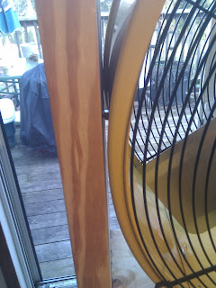
On a side note I think I found a decent use for the carts that the fans came on, these little plastic trays are pretty wobbly when you get them full of plants that just got watered, and they are the perfect size to set in the cart comfortably. I'm going to take the left over plywood and make a platform so that they can sit even on top of it, but otherwise this will be great for me to pull them out during the day so they can get some sun, but bring them in at night so they don't get too cold or wind blown without worrying if the tray is going to buckle under the load and kill all my seedlings from dropping 3 feet to the floor.
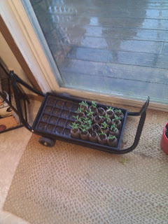 |
| I really think I'm going to get some decent peppers this year! At least, I hope anyways. |